Programming #
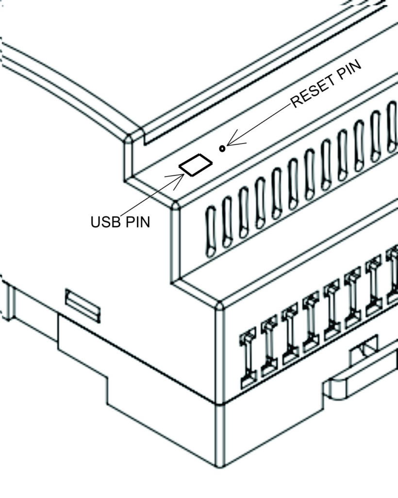
The NORVI IIOT-AE01-R has a mini USB Port for serial connection with the SoC for programming. Any ESP32-supported programming IDE can be used to program the controller. Follow this Guide to programming NORVI ESP32-based controllers with the Arduino IDE.
SoC: ESP32-WROOM32
Programming Port: USB UART
Digital Inputs #
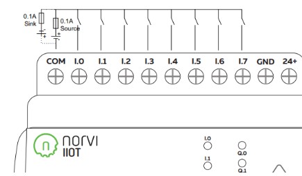
Wiring Digital Inputs #
The digital inputs of NORVI IIOT-AE01-R can be configured as both Sink and Source connections. The inverse of the Digital Input polarity should be supplied to the common terminal.
Programming Digital Inputs #
Reading the relevant GPIO of the ESP32 gives the value of the Digital Input. When the inputs are in the OFF state, the GPIO goes HIGH, and when the input is in the ON state, the GPIO goes LOW.
Refer to the GPIO allocation table in the Datasheet for the digital input GPIO.
#define INPUT1 18

void setup() {
  Serial.begin(115200);
  Serial.println("Device Starting");
  pinMode(INPUT1, INPUT);
}

void loop() {
  Serial.print(digitalRead(INPUT1));
  Serial.println("");
  delay(500);
}
Relay / Transistor Output #
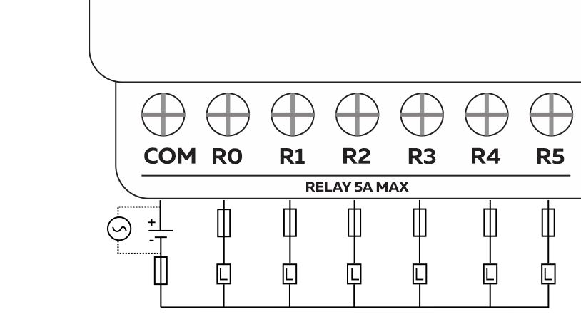
Wiring Relay Outputs #
Wiring Transistor Outputs #
Programming Relay/ Transistor Outputs #
Reading the relevant GPIO of the ESP32 gives the value of the relay or transistor output. Refer to the GPIO allocation table in the Datasheet for the relay/transistor output GPIO.
#define OUTPUT1 14

void setup() {
  Serial.begin(115200);
  Serial.println("Device Starting");
  pinMode(OUTPUT1 , OUTPUT);
}

void loop() {
  digitalWrite(OUTPUT1, HIGH);
  delay(500);
  digitalWrite(OUTPUT1, LOW);
  delay(500);
  Serial.println("");
  delay(500);
}
RS-485 communication #
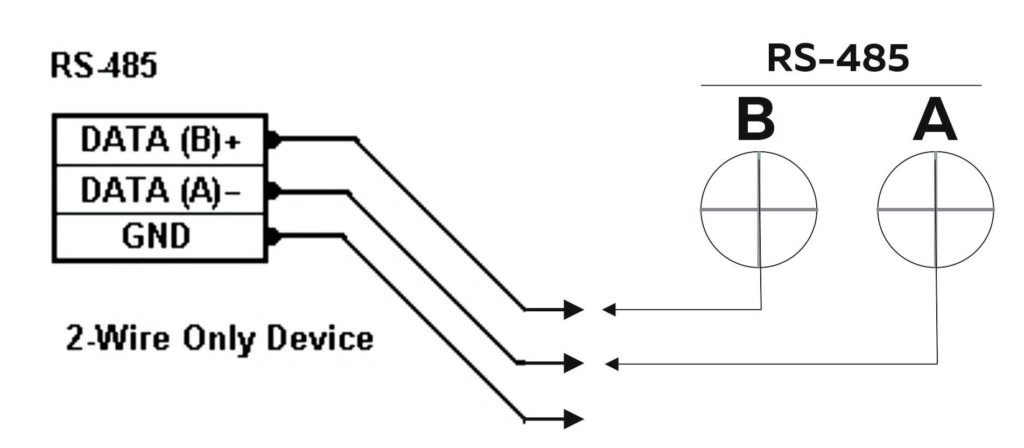
RS-485 Wiring #
| Driver | MAX485 |
| UART RX | GPIO3 |
| UART TX | GPIO1 |
| Flow Control | GPIO4 |
Programming RS-485 #
The UART Connections of RS-485 in the NORVI IIOT-AE01 series are shared with the UART connections of USB Serial.
NORVI-IIOT-AE01 and NORVI-IIOT-AE02 product ranges utilize RS485 communication where the TX (Transmit) and RX (Receive) pins are shared with the USB RX and TX pins. This means that the same physical pins are used for both serial communication with a computer via USB and RS485 communication.
As a result, direct use of serial print functions for communication is not possible when connected to such devices. An alternative solution would be to output the result to an OLED display, providing visual feedback on the data.
#include <Wire.h>
#include <Adafruit_SSD1306.h>
#include <Adafruit_GFX.h>

#define FC 4
#define RXD 3
#define TXD 1

#define SCREEN_WIDTH 128
#define SCREEN_HEIGHT 64
#define OLED_RESET    -1
Adafruit_SSD1306 display(SCREEN_WIDTH, SCREEN_HEIGHT, &Wire, OLED_RESET);

void setup() {
  Serial.begin(9600);
  pinMode(FC, OUTPUT);
  digitalWrite(FC, LOW);

  Wire.begin(16, 17);
  display.begin(SSD1306_SWITCHCAPVCC, 0x3C);
  display.display();
}

void loop() {
  Serial1.println(F("RS485 01 SUCCESS"));
  while (Serial.available()) {  // Check if data is available
    char c = Serial.read();     // Read data from RS485
    display.clearDisplay();
    display.setTextColor(WHITE);
    display.setTextSize(1);
    display.setCursor(0, 12);
    display.print(c);
    delay(100);
    display.display();
  }
}
Built-in OLED Display #
| Display driver | SSD1306 |
| Communication | I2C |
| Module Address | 0x3C |
| Resolution | 128 x 64 |
Refer to the GPIO allocation table in the datasheet for the I2C GPIO of the OLED Display.
Library supported by the Adafruit_SSD0306 Library.
Wire.begin (SDA, SCL); is required to initialize I2C on correct pins.
Programming OLED Display #
#include <SPI.h>
#include <Wire.h>
#include <Adafruit_GFX.h>
#include <Adafruit_SSD1306.h>
#define SCREEN_WIDTH 128 // OLED display width, in pixels
#define SCREEN_HEIGHT 64 // OLED display height, in pixels
// Declaration for an SSD1306 display connected to I2C (SDA, SCL pins)
#define OLED_RESET     -1 // Reset pin # (or -1 if sharing Arduino reset pin)
Adafruit_SSD1306 display(SCREEN_WIDTH, SCREEN_HEIGHT, &Wire, OLED_RESET);

void setup() {
  Wire.begin(16,17);
  if(!display.begin(SSD1306_SWITCHCAPVCC, 0x3C)) { // Address 0x3C for 128x64
    Serial.println(F("SSD1306 allocation failed"));
    for(;;); // Don't proceed, loop forever
  }
  // Show initial display buffer contents on the screen --
  // the library initializes this with an Adafruit splash screen.
  display.display();
  delay(2000); // Pause for 2 seconds
  }

void loop() {
}
Built-in Buttons #
| Read mode | ADC (Analog to Digital Conversion) |
| Analog IO | GPIO32 |
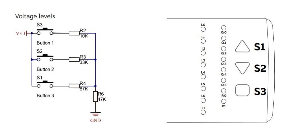 |
Programming Buttons #
#define buttonPin 32
int  buttonState = 0;

void setup() {
  Serial.begin(9600);
  pinMode(buttonPin,INPUT);
}

void loop() {
  Serial.print("Button: ");
  buttonState = analogRead(buttonPin);
  delay(50);
  Serial.print(analogRead(buttonPin));
  Serial.print("\tAnalog: ");
  delay(1000);
}
USB and Reset #