Product Features #
- Quad-Channel Analog Outputs
- 12-bit Analog Values can be written
- I2C Master can command
- Built-in Diagnostics and Alert Features.
- Robust Architecture.
- DIN-Rail mount
Expansions Supported
- Analog Output
Main #
| Range of Product | NORVI Expansion |
| Product Type | Expansion Module |
| Certifications | EN 61131-2:2007 EN 61010-1:2010+A1:2019 EN IEC 61010-2-201:2018 2014/30/EU- Electromagnetic Compatibility (EMC) Annex III, Part B, Module C |
| Rated supply voltage | 24V DC |
| Communication | I2C |
| Inputs and Outputs | 4 x Analog Outputs |
| Displays and Visual Indicators | LED green, red |
Complementary #
| Product Unified Code | NORVI-EX-ANQ-04 |
| Product Part Numbers | NORVI-EX-ANQ-04 |
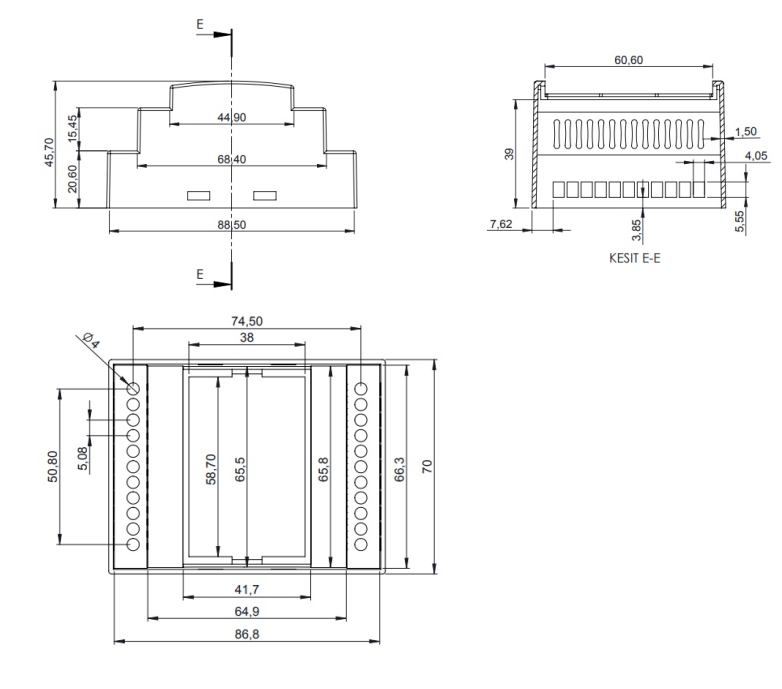
Mechanical Properties #
| Enclosure | NORVI 204 |
| Mounting / Installation Method | DIN RAIL / MOUNTING TABS |
| Terminal Type | Top hat type TH35-15 rail conforming to IEC 60715 Top hat type TH35-7.5 rail conforming to IEC 60715 Plate or panel with fixing kit |
| Terminal Arrangement | Top and Bottom |
| Length | 90.50 mm |
| Height | 56.60 mm |
| Width | 60.60 mm |
Environment #
| IP degree of protection | IP20 |
| Operating altitude | 0 – 2000 meters |
| Operating Temperature | –10 … +85° C (14…185 °F) |
| Storage altitude | 0 – 3000 meters |
| Shock resistance | 15 gn for 11ms |
| Resistance to electrostatic discharge | 4kV on contact 8kV on air |
| Resistance to electromagnetic fields | 10 V/m (80 MHz …… 1GHz) 3 V/m (1.4 MHz …… 2 GHz) 1 V/m (2 MHz …… 3 GHz) |
Electrical Characteristics #
Grid Powered Devices #
| Rated Supply Voltage (V) | 24V DC |
| Current Consumption (mA) | 400mA |
| Recommended Power Source | 1A 24V DC |
Processing #
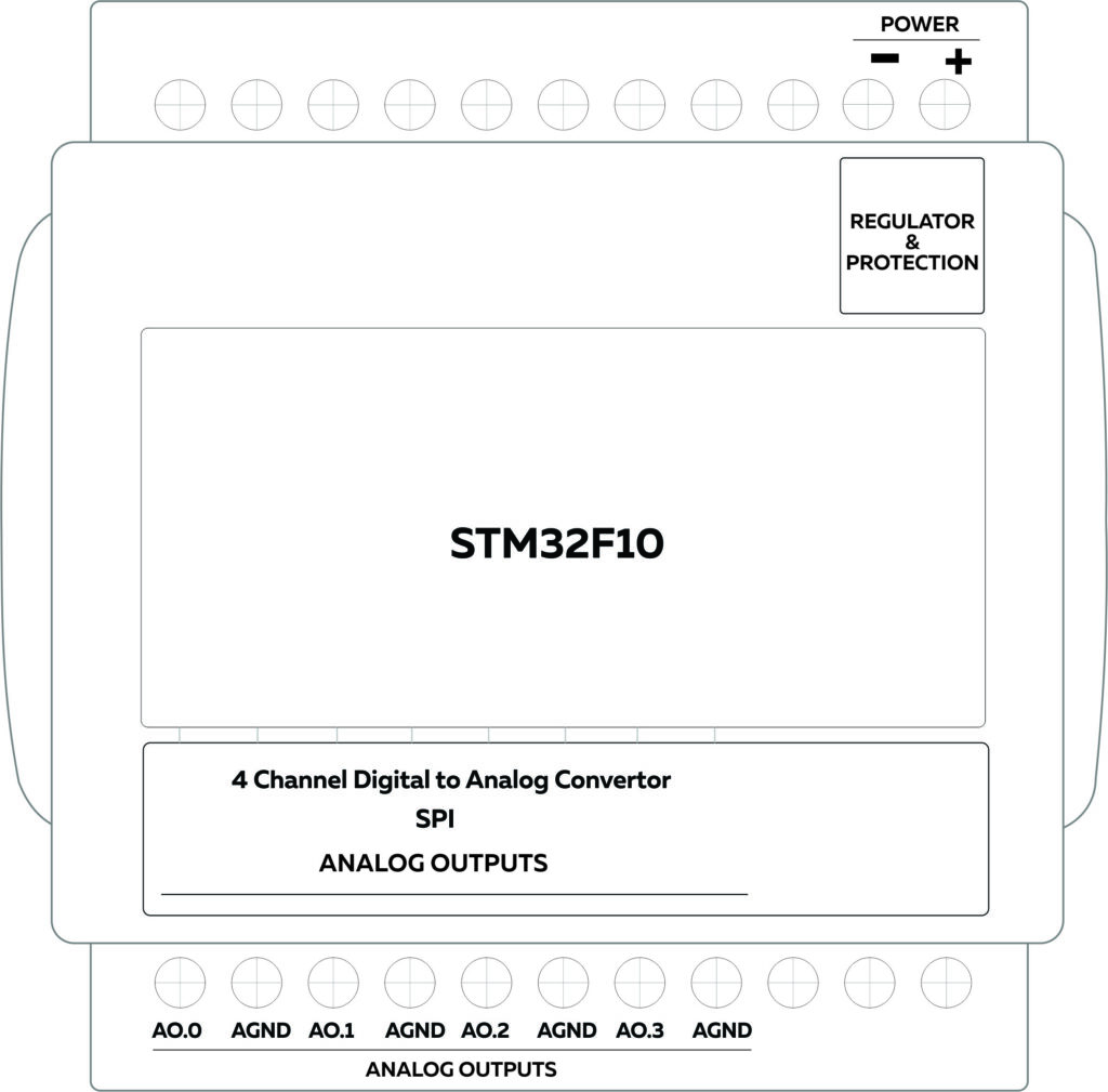
| SOC / MCU | STM32F103x8 |
| Flash Memory | 128 Kb |
| SRAM | 20 Kb |
INPUTS and OUTPUTS #
Analog Outputs #
| Module | AD74413R | |
| Module type | Quad-Channel Analog Outputs | |
| Number of Analog Output Channels | 4 | |
| output configuration of channels | 0 = 0 – 10V Output | 1 = 4 – 20mA Output |
| DAC Communication | I2C | |
| Terminal Arrangement | 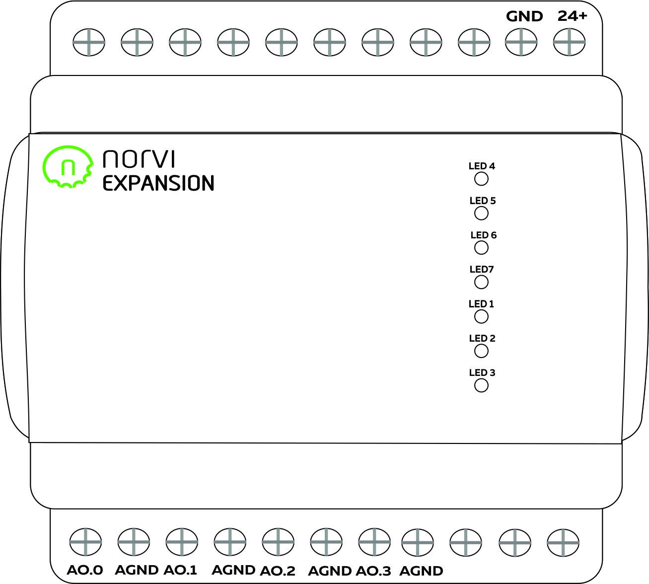 | |
SMD Crystal #
| Module | LFXTAL003166 |
| Module type | External Oscillator |
| Frequency | 10MHz |
| In 1 | PC14 |
| Out 1 | PC15 |
| In 2 | PD0 |
| Out 2 | PD1 |
Indicators #
| LED1 | ALERT |
| LED2 | ADC_RDY |
| LED3 | GND |
| LED4 | PA15 |
| LED5 | PB3 |
| LED6 | PB4 |
| LED7 | PB5 |
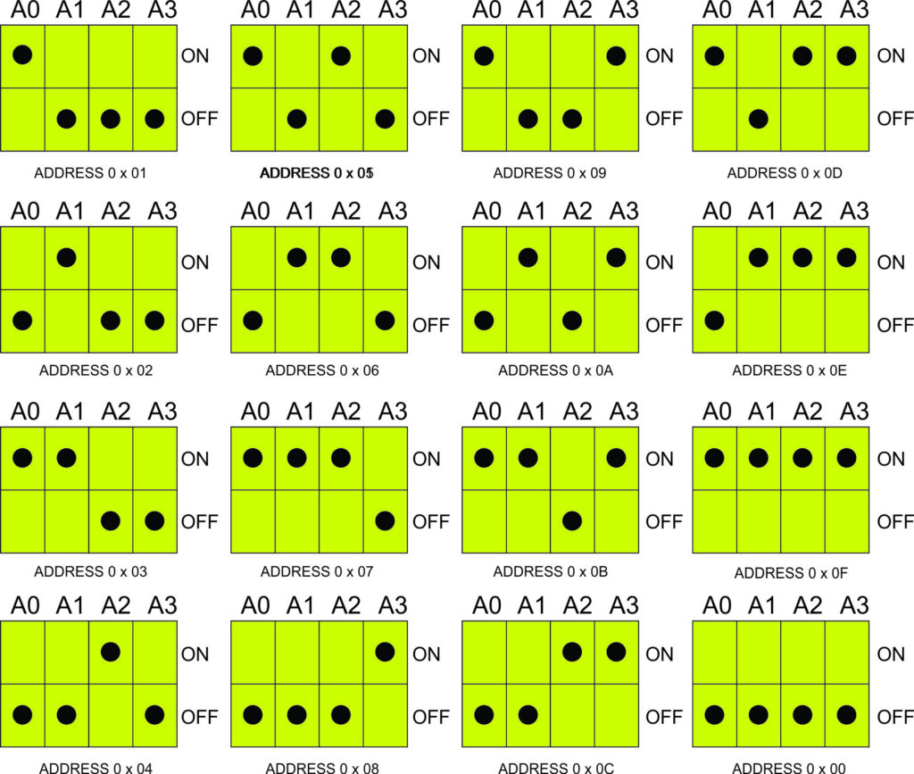
I2C Address Setting #
The I2C address of the expansion module can be configured by switching DIP switches at the bottom of the expansion module. The device can be configured at 8 I2C addresses using the first 3 DIP switches.
I2C Control From a master #
| Control Register | ||
|---|---|---|
| Bit Position | Description | Values |
| B7 | ||
| B6 | ||
| B5 | ||
| B4 | ||
| B3 | Analog Channel D Config | 0 = 0 – 10V 1 = 4 – 20mA |
| B2 | Analog Channel C Config | 0 = 0 – 10V 1 = 4 – 20mA |
| B1 | Analog Channel B Config | 0 = 0 – 10V 1 = 4 – 20mA |
| B0 | Analog Channel A Config | 0 = 0 – 10V 1 = 4 – 20mA |
| Status Register | |||
| Bit Position | Description | 0 – 10V Output Mode | 4 – 20mA Output Mode |
| B7 | AVDD Power Supply Monitor Error. | ||
| B6 | Power Supply Monitor Error | ||
| B5 | Charge pump error detected | ||
| B4 | High temperature detected | ||
| B3 | Channel D Status | 1 = Short Circut 0 = Normal | 1 = Open Circut 0 = Normal |
| B2 | Channel C Status | 1 = Short Circut 0 = Normal | 1 = Open Circut 0 = Normal |
| B1 | Channel B Status | 1 = Short Circut 0 = Normal | 1 = Open Circut 0 = Normal |
| B0 | Channel A Status | 1 = Short Circut 0 = Normal | 1 = Open Circut 0 = Normal |
| Bit Position | B7 | B6 | B5 | B4 | B3 | B2 | B1 | B0 |
| Analog Output 1 | 12-bit ADC Code Last 12 bits will affect the output 4095 = 10V / 20mA 0 = 0V / 0mA | |||||||
| Analog Output 1 | ||||||||
| Analog Output 1 | ||||||||
| Analog Output 1 | ||||||||
GPIO Map #
| Pin | GPIO | Usage | |
| 3 | PC14 | Oscillator 1 | In |
| 4 | PC15 | Oscillator 1 | Out |
| 5 | PD0 | Oscillator 2 | In |
| 6 | PD1 | Oscillator 2 | Out |
| 7 | NRST | Button | Reset |
| 14 | PA4 | AD744 | SYNC |
| 15 | PA5 | AD744 | SCLK |
| 16 | PA6 | AD744 | SD1 |
| 17 | PA7 | AD744 | SA0 |
| 20 | PB2 | BOOT1 | |
| 25 | PB12 | AD744 | Reset |
| 26 | PB13 | AD744 | Alert |
| 27 | PB14 | AD744 | ADC_Ready |
| 28 | PB15 | DIP switch | NO_4 |
| 29 | PA8 | DIP switch | NO_3 |
| 30 | PA9 | DIP switch | NO_2 |
| 31 | PA10 | DIP switch | NO_1 |
| 32 | PA11 | USB | D- |
| 33 | PA12 | USB | D+ |
| 38 | PPA15 | Indicators | LED4 |
| 39 | PB3 | Indicators | LED5 |
| 40 | PB4 | Indicators | LED6 |
| 41 | PB5 | Indicators | LED7 |
| 42 | PB6 | SCL | |
| 43 | PB7 | SDA | |
| 44 | BOOT0 |
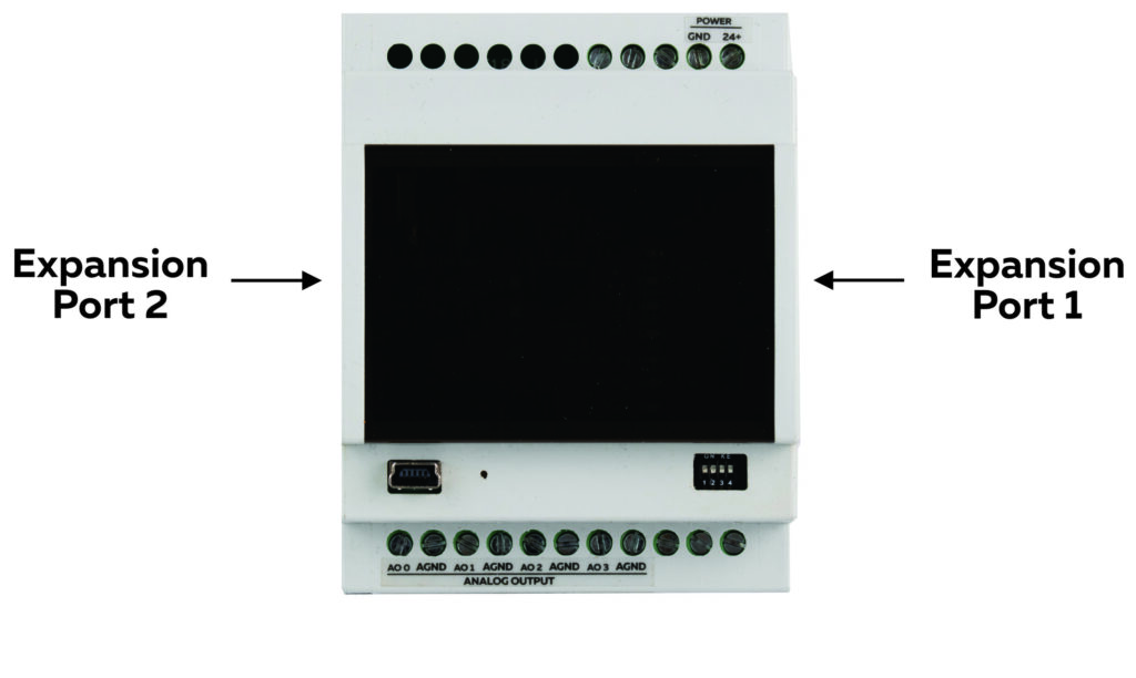
Expansion Port #
The expansion port of the NORVI Controllers can be utilized for external sensor connections where raw GPIO connections are required or they can be used to plug NORVI Expansion Modules.
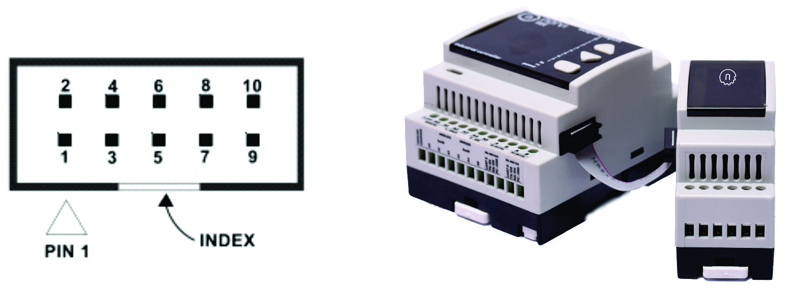
| PIN | Connections Port 1 | Connections Port 2 |
| 1 | GPIO33 | SDA |
| 2 | TXD0 | GND |
| 3 | EX1 | SCL |
| 4 | RXD0 | EX2 |
| 5 | NRST | GPIO32 |
| 6 | GPIO32 | NRST |
| 7 | EX2 | RXD0 |
| 8 | SCL | EX1 |
| 9 | GND | TXD0 |
| 10 | SDA | GPIO33 |


