Product Features #
- Arduino Micro ATMEGA 32
- Built-in 0.96 OLED Display
- Built-in Button on the front panel
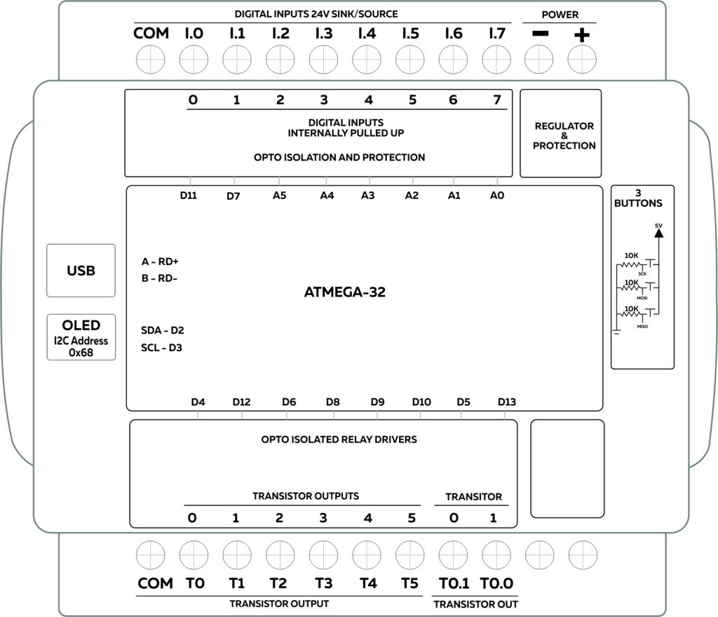
- Digital Inputs
- Transistor Outputs
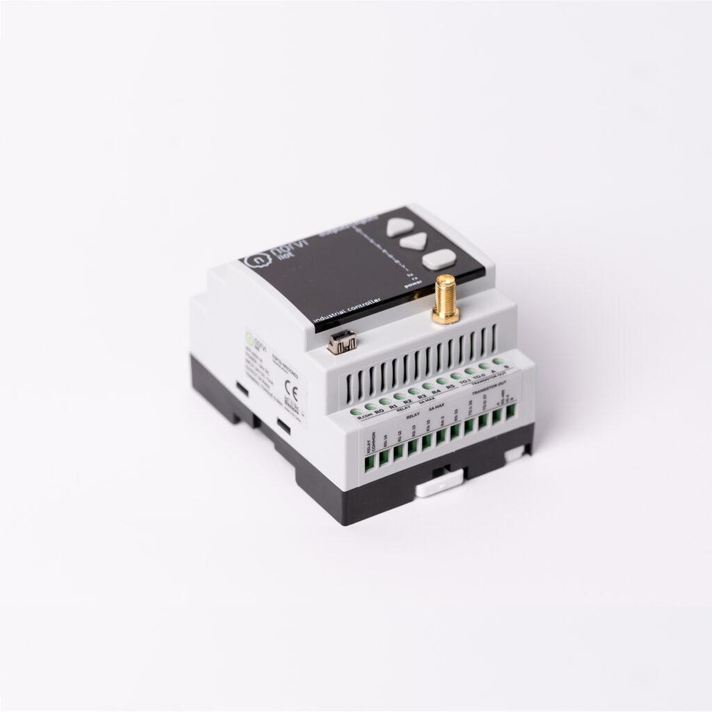
- DIN-Rail mount
Main #
| Range of Product | NORVI CEMA |
| Product Type | Programmable Controller |
| Certifications | EN 61131-2:2007 EN 61010-1:2010+A1:2019 EN IEC 61010-2-201:2018 2014/30/EU- Electromagnetic Compatibility (EMC) Annex III, Part B, Module C |
| Rated supply voltage | 24V DC |
| Communication | WiFI / Bluetooth |
| Inputs and Outputs | 8 x Digital Inputs 8 x Transistor Outputs |
| Displays and Visual Indicators | 0.96 OLED Display and Indicators |
Complementary #
| Product Unified Code | NORVI CEMA-M2 |
| Product Part Numbers | NORVI CEMA-M2 |
Mechanical Properties #
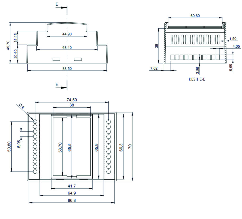
| Enclosure | NORVI 204 |
| Mounting / Installation Method | DIN RAIL / MOUNTING TABS |
| Terminal Type | SCREW TERMINAL |
| Terminal Arrangement | Top and Bottom |
| Length | 90.50 mm |
| Height | 56.60 mm |
| Width | 60.60 mm |
Environment #
| IP degree of protection | IP20 |
| Operating altitude | 0 – 2000 meters |
| Operating Temperature | – –10 … +85° C (14…185 °F) |
| Storage altitude | 0 – 3000 meters |
| Shock resistance | 15 gn for 11ms |
| Resistance to electrostatic discharge | 4kV on contact 8kV on air |
| Resistance to electromagnetic fields | 10 V/m (80 MHz …… 1GHz) 3 V/m (1.4 MHz …… 2 GHz) 1 V/m (2 MHz …… 3 GHz) |
Electrical Characteristics #
Grid Powered Devices #
| Rated Supply Voltage (V) | 24V DC |
| Current Consumption (mA) | 400mA |
| Recommended Power Source | 1A 24V DC |
Processing #
| SOC / MCU | Arduino Micro ATMEGA 32 |
| Flash Memory | 32KB |
| EEPROM | 512Bytes/1KB |
| SRAM | 1.25/2.5KB |
| Maximum Clock Frequency | 16 MHz |
Peripherals #
Built-in Buttons #
| Button 1 Pin | SCK |
| Button 2 Pin | MOSI |
| Button 3 Pin | MISO |
OLED Display #
| Display Driver | SSD1306 |
| Display Size | 0.96 inch |
| SCL PiN | D3 |
| SDA Pin | D2 |
| RESET Pin | NOT CONNECTED |
INPUTS and OUTPUTS #
Digital Inputs #
| Number of Digital Inputs | 8 |
| Digital Input Polarity | Sink and Source |
| Digital Input Maximum Voltage | 32V DC |
| Digital Input Minimum Voltage | 18V DC |
| Maximum Switching Frequency | 1 kHZ |
| Terminal Arrangement | Digital Input 0 – D11 Digital Input 1 – D7 Digital Input 2 – A5 Digital Input 3 – A4 Digital Input 4 – A3 Digital Input 5 – A2 Digital Input 6 – A1 Digital Input 7 – A0 |
Transistor Outputs #
| Number of Transistor Outputs | 2 |
| Transistor Output Type | OPEN COLLECTOR |
| Maximum Sink/Source Current (mA) | 100mA |
| Maximum Applicable Voltage | 40V DC |
| Maximum Switching Frequency | 1 kHz |
| Terminal Arrangement | Transistor Output 0.0 – D5 Transistor Output 0.1 – D13 Transistor Output 0 – D4 Transistor Output 1 – D12 Transistor Output 2 – D6 Transistor Output 3 – D8 Transistor Output 4 – D9 Transistor Output 5 – D10 |
GPIO Map #
| Pin | GPIO | Description | Usage |
| 1 | D7 | input only | Digital Input 1 |
| 3 | RD+ | USB | A |
| 4 | RD- | USB | B |
| 8 | RXLED | LED | RX |
| 9 | Button 1 | SCK | |
| 10 | Button 2 | MOSI | |
| 11 | Button 3 | MISO | |
| 12 | D11 | input only | Digital Input 0 |
| 16 | XTAL2 | OSCIN | |
| 17 | XTAL1 | OSCOUT | |
| 18 | D3 | SCL | |
| 19 | D2 | SDA | |
| 20 | D0 | RX1 | |
| 21 | D1 | TX1 | |
| 22 | TXLED | LED | TX |
| 25 | D4 | Transistor Output 0 | |
| 26 | D12 | Transistor Output 1 | |
| 27 | D6 | Transistor Output 2 | |
| 28 | D8 | Transistor Output 3 | |
| 29 | D9 | Transistor Output 4 | |
| 30 | D10 | Transistor Output 5 | |
| 31 | D5 | Transistor output 0.0 | |
| 32 | D13 | Transistor output 0.1 | |
| 36 | A0 | input only | Digital Input 7 |
| 37 | A1 | input only | Digital Input 6 |
| 38 | A2 | input only | Digital Input 5 |
| 39 | A3 | input only | Digital Input 4 |
| 40 | A4 | input only | Digital Input 3 |
| 41 | A5 | input only | Digital Input 2 |


