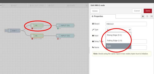
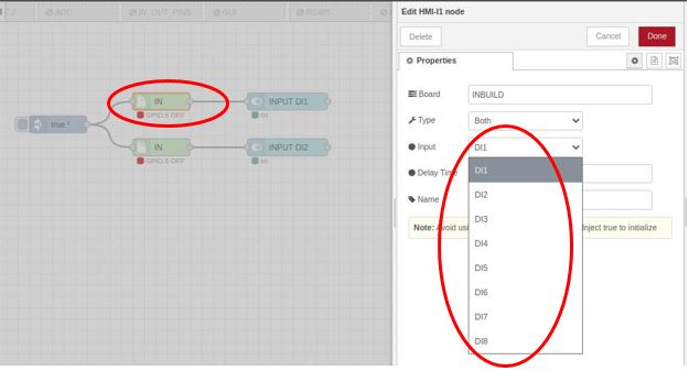
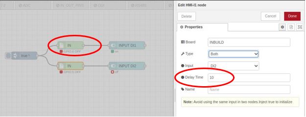
The HMI-I1 node serves as a digital input node, representing the inputs of the HMI. It generates a “msg. payload” with either a 0 or 1 depending on the state of the input pin. Configuration of this node involves selecting the desired input.
Inputs: msg. payload (Boolean) – The payload will be a TRUE or a FALSE.
Outputs: msg. payload (Boolean) – The payload will be a TRUE or a FALSE.
TRIGGER TYPE: RISING, FALLING, BOTH
INPUT = SELECT INPUT NUMBER
Lorem ipsum dolor sit amet, consectetur adipiscing elit. Ut elit tellus, luctus nec ullamcorper mattis, pulvinar dapibus leo.
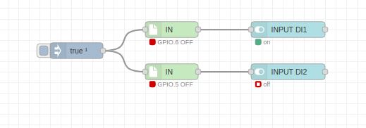
Example Program: Raspberry Pi HMI Node-RED - Controlling Digital Inputs
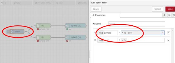
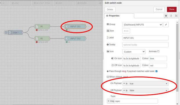
Let’s create a simple example program using the RPI-HMI-IN node. When a button is pressed it contains true and false and this represents a trigger. Here, to display the program in the Node-RED dashboard added a switch node (digi 01 & digi 02) to it as a dashboard node.
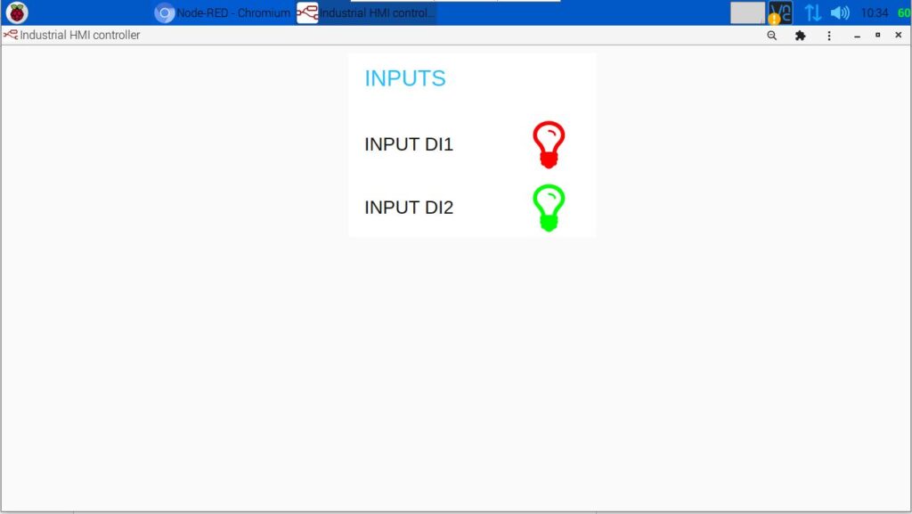
After setting the configuration of the program, the user interface of the RPI HMI should be as below.
Digital Input 1 ON and Digital Input 2 OFF
Digital Input 1 OFF and Digital Input 2 ON
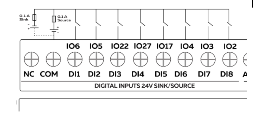
This schematic shows the connection between the RPI-HMI inputs. When the inputs are in the OFF state, the GPIO goes LOW, and when the input is in the ON state, the GPIO goes HIGH.