Example of Node-Red on RPI HMI applications. NORVI has a set of node-red nodes that makes programming easy.
Here is an example of using the Raspberry PI HMI Transistor Outputs ON and OFF node for Node-RED. This node facilitates the control of NORVI-RPI-HMI outputs. Check out How Node-Red on RPI HMI works.
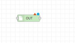
The HMI-Q1 node serves as a digital output node. It accepts a “msg. payload” with either a 0 or 1, setting the selected physical pin high or low based on the passed value.
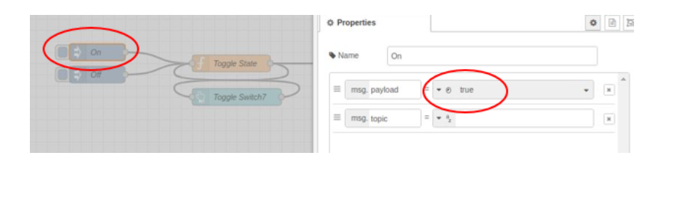
Inputs: payload number | string | Boolean When sending a message to the Node-RED HMI-Q1 node, use any of these inputs to control the output. For example, sending Boolean true turns the output on, and sending Boolean false turns it off. Similarly, sending either the number 1 or the string “ON” can turn the output on, depending on how the flow is configured.
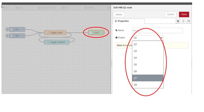
Output = Desired output can be selected in node configuration.
Example of Node-Red on RPI HMI
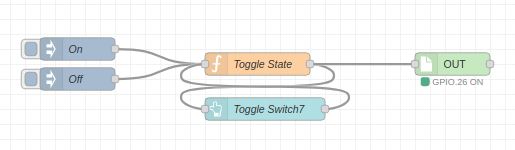
Let’s create a simple example program using the RPI-HMI-OUT node. When a button is pressed, it contains true and false values, representing a trigger. Display the program on the Node-RED dashboard by adding a switch node (Q7 ON & Q7 OFF) as a dashboard node.
To display the program in the Node-RED dashboard add a button node (Toggle Switch7) to it as a dashboard node.
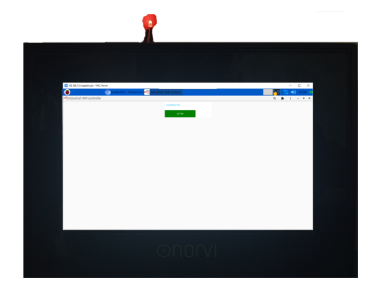
After setting the configuration of the program, the user interface of the RPI HMI should be as below.
ON state – When the output is in the ON state, it means the output is activated, and the LED associated with it is illuminated.
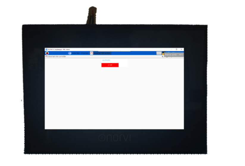
OFF state – When the output is in the OFF state, it means the output is deactivated, and the LED associated with it is turned off.
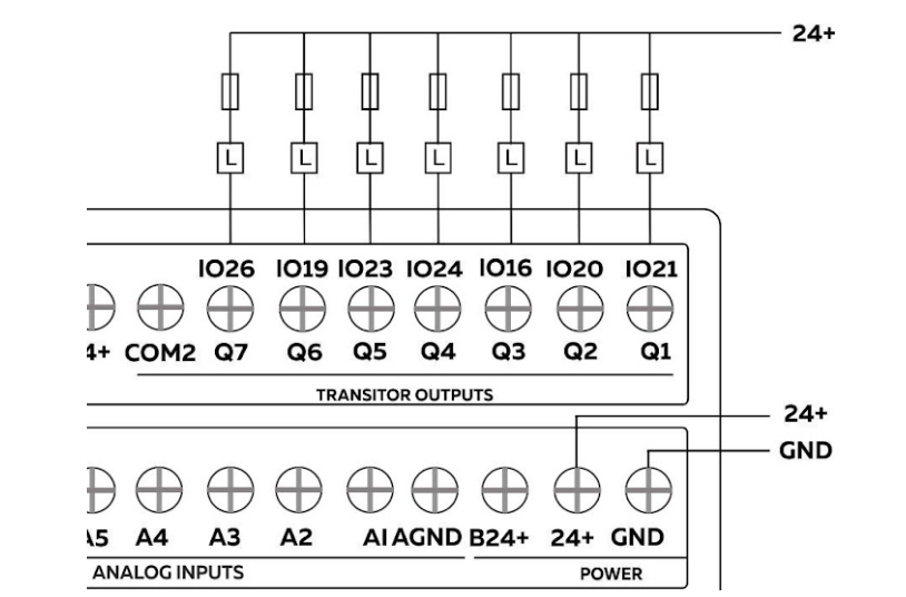
This schematic shows the connection between the RPI-HMI output and the LED. The RPI-HMI output is connected to the GND end of the LED, while the other end of the LED is connected to a resistor, and then to the power in(24+).