In this article, we explore how to use ESP32 PLC PWM Outputs to regulate motor speeds efficiently using NORVI IIOT Device, equipped with an ESP32-WROOM32 module.
With its built-in features like OLED display, digital and analog inputs, relay outputs, and DIN-rail mount, NORVI IIOT proves to be a versatile platform for motor control applications.

PWM stands for Pulse Width Modulation. It is a modulation technique used to encode a message into a pulsing signal.
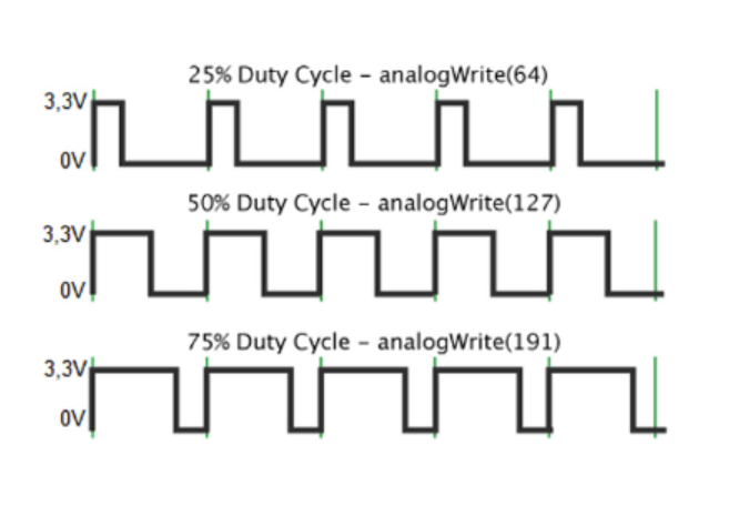
In PWM, the digital signal is turned on and off at a certain frequency with varying pulse widths, or duty cycles.
The duty cycle refers to the percentage of time the signal is on (high) compared to the total period of the signal.
PWM is commonly used in various applications,
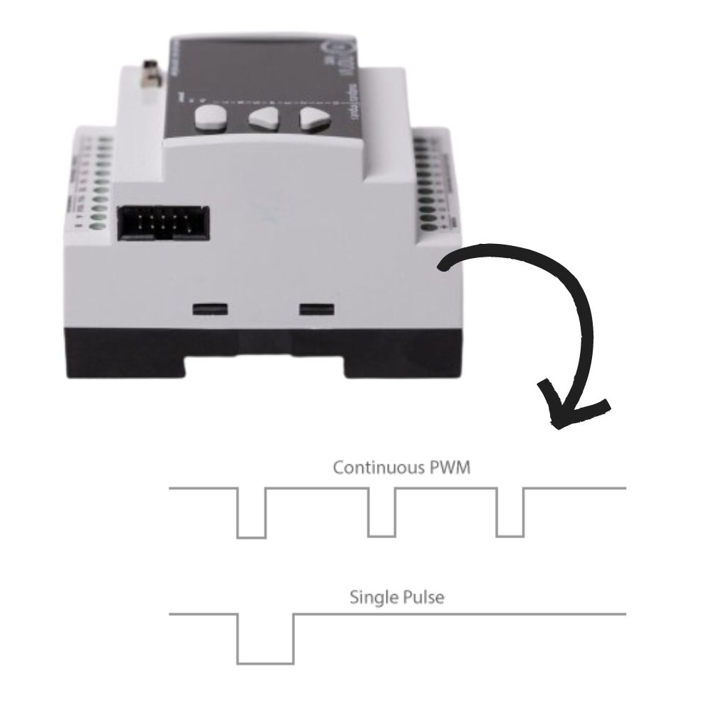
As an example, In motor control applications, PWM is used to control the speed of motors by varying the average voltage or current supplied to the motor. By adjusting the duty cycle of the PWM signal, the effective power delivered to the motor can be controlled, thus regulating its speed.
PWM offers several advantages,

The ESP32 microcontroller, which features a dual-core processor and Wi-Fi/Bluetooth connectivity, offers flexible PWM (Pulse Width Modulation) capabilities suitable for various applications.
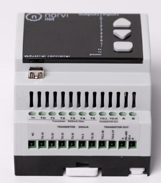
The ESP32 provides multiple PWM channels, allowing simultaneous control of multiple devices or components. Here’s an overview of the ESP32 PLC PWM Outputs:

In the context of motor control, PWM is used to regulate the power supplied to the motor by controlling the average voltage and current through varying the duty cycle of the signal. A higher duty cycle translates to a higher average voltage and vice versa, thus controlling the speed of the motor.
Let’s look into the process of how ESP32 PLC PWM Outputs are used for controlling the Motor speeds.
By using the ESP32 PWM outputs of the NORVI IIOT device, associated with its advanced features and capabilities, system integrators, engineers and developers can effectively regulate motor speeds in industrial applications. Whether it’s for controlling conveyor belts, pumps, fans, or other motor-driven equipment, NORVI IIOT provides a reliable platform for achieving precise and efficient motor control, ultimately contributing to improved productivity and operational performance in industrial settings.
If you have any questions, Please reach our technical team at support@icd.lk
VISIT OUR Product Pages to get More Information: NORVI IIOT & NORVI ESP32 HMI
We use cookies to improve your experience on our site. By using our site, you consent to cookies.
Websites store cookies to enhance functionality and personalise your experience. You can manage your preferences, but blocking some cookies may impact site performance and services.
Essential cookies enable basic functions and are necessary for the proper function of the website.
Google reCAPTCHA helps protect websites from spam and abuse by verifying user interactions through challenges.
Google Tag Manager simplifies the management of marketing tags on your website without code changes.
WooCommerce is a customizable eCommerce platform for building online stores using WordPress.
Statistics cookies collect information anonymously. This information helps us understand how visitors use our website.
Google Analytics is a powerful tool that tracks and analyzes website traffic for informed marketing decisions.
Service URL: policies.google.com
SourceBuster is used by WooCommerce for order attribution based on user source.
Marketing cookies are used to follow visitors to websites. The intention is to show ads that are relevant and engaging to the individual user.
You can find more information in our Cookie Policy and NORVI CONTROLLERS Privacy Policy.